
Measuring procedure is a key factor for our constant development. Experimental measurements are necessary for the creation of graphs.
These measurements were made according to the European Standard CYS EN 12238:2001 in an effort to determine throw, drop and spread for each value of the supply. This research project concerns the certification of air conditioning outlets of grilles, which were experimentally tested and computationally simulated. The certification concerns the control of air supply of each discharge and developing the right spans in order, for the room to be in the desired temperature of comfort, i.e. providing the distance in length that will reach the air but also in finding the width (opening) of the outflow. At the same time, measurements of the noise levels for different air flows were established. Furthermore, for each supply, measurement of the air pressure took place in order to determine the pressure difference Δp, which requires calculations from manometer fans in air conditioning systems or the various sites. Moreover, the technical characteristics of the grille masured for air exit velocity from the grille minimum value of Vc =1 to 2 m/s up to a maximum value of Vc = 10 m/s.
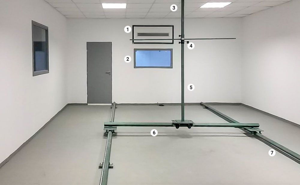
Measuring chamber (chamber dimensions: 10,0 x 5,5 x 2,75 m = 151,25 m²). The measuring chamber is a metallic and sensored support scaffold system with motion in three axes, in order to be able to process an interior full scan of the interior of the test chamber. The measuring chamber is capable to test outlet surfaces of any kind (linear, with aerostats, curved with fins, jet nozzles, etc.), with maximum dimensions 1,20 X 0,55 m. Also, provision is made for ceiling orifices study of any kind with maximum dimensions 1,20 X 1,20 m. Figure below shows the laboratory area.
The main elements that characterize the industrial area are:
1. Window benefit adjustment hall
2. Grille Wall
3. Orifice room
4. Installation location measuring instrument
5. Z-Axis
6. Y-Axis
7. X-Axis
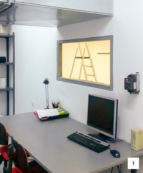
1. Measuring Room
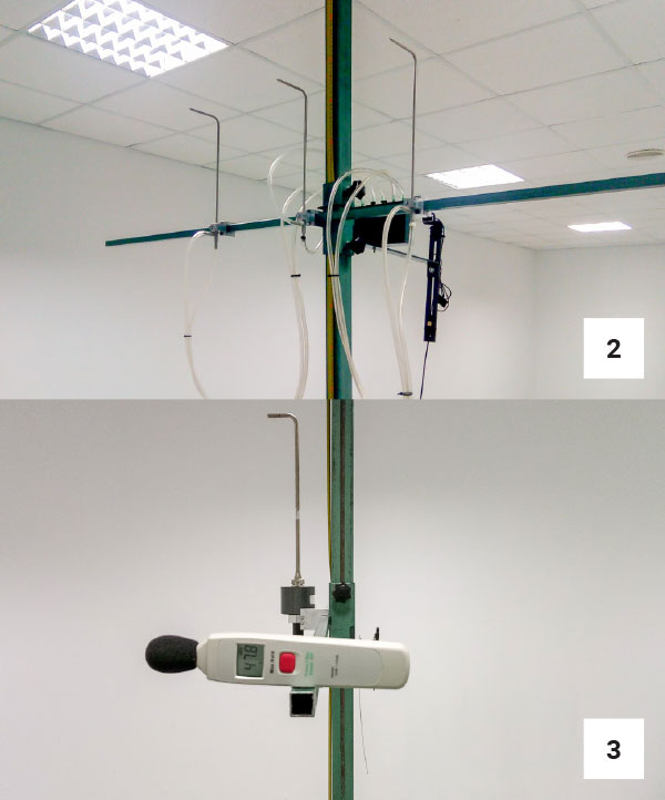
2. Pitot-static tube gauge during measuring
3. Sound meter
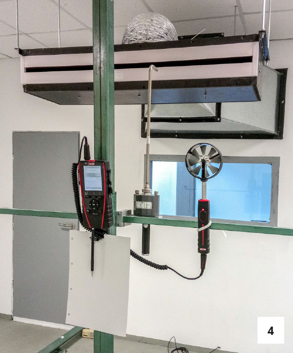
4. Pitot-static tube and MP210 Digital Pressure Gauge
| Cookie | Duration | Description |
|---|---|---|
| cookielawinfo-checkbox-analytics | 11 months | This cookie is set by GDPR Cookie Consent plugin. The cookie is used to store the user consent for the cookies in the category "Analytics". |
| cookielawinfo-checkbox-functional | 11 months | The cookie is set by GDPR cookie consent to record the user consent for the cookies in the category "Functional". |
| cookielawinfo-checkbox-necessary | 11 months | This cookie is set by GDPR Cookie Consent plugin. The cookies is used to store the user consent for the cookies in the category "Necessary". |
| cookielawinfo-checkbox-others | 11 months | This cookie is set by GDPR Cookie Consent plugin. The cookie is used to store the user consent for the cookies in the category "Other. |
| cookielawinfo-checkbox-performance | 11 months | This cookie is set by GDPR Cookie Consent plugin. The cookie is used to store the user consent for the cookies in the category "Performance". |
| viewed_cookie_policy | 11 months | The cookie is set by the GDPR Cookie Consent plugin and is used to store whether or not user has consented to the use of cookies. It does not store any personal data. |